
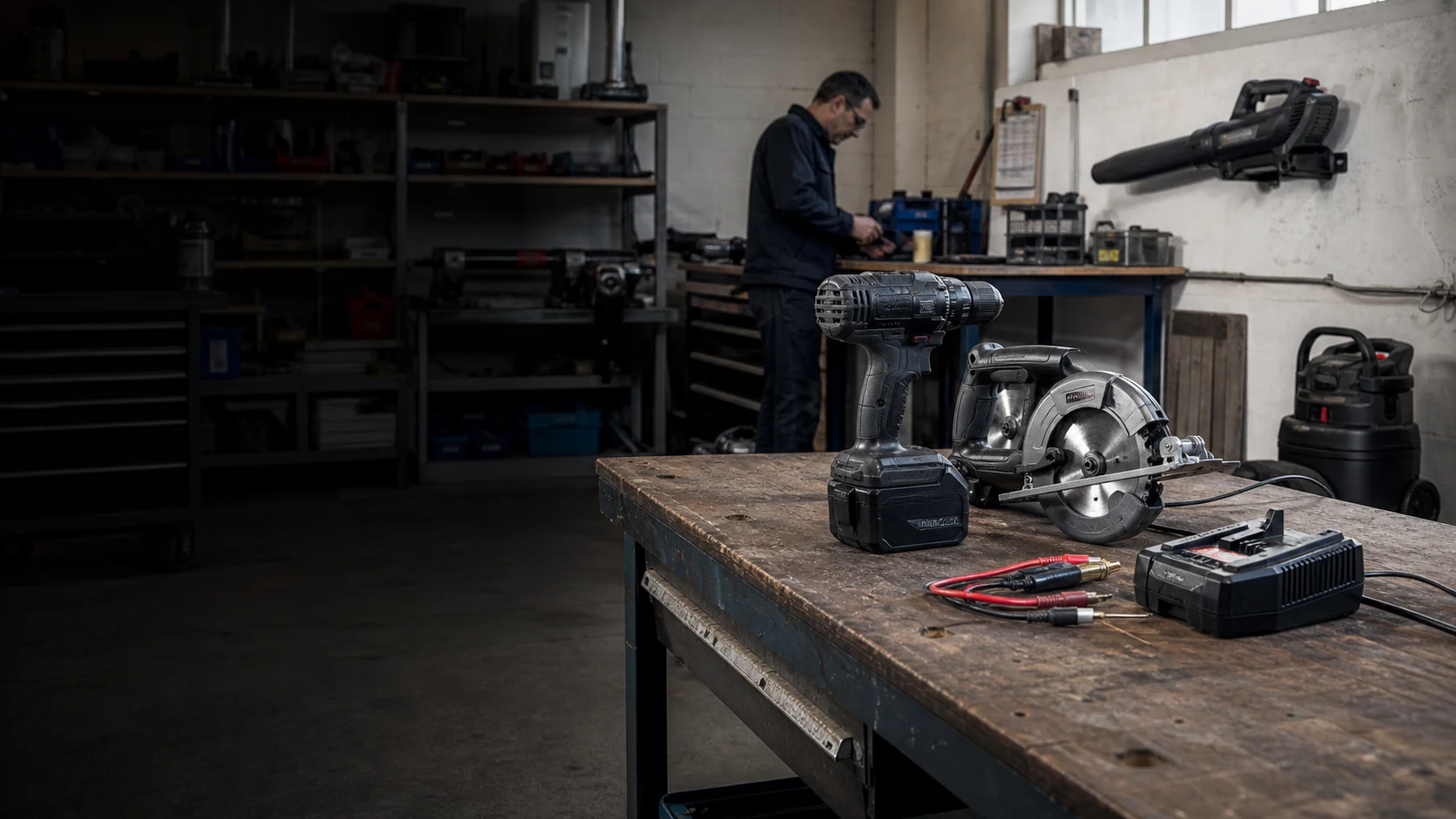
POWER TOOL & SMALL EQUIPMENT BATTERY APPLICATIONS
Battery Systems Built Around the Equipment, Load and Duty Cycle.
Define the tool or machine family, peak and continuous load, enclosure and interface, charger and working environment first. Then coordinate the battery and validation path around the complete equipment platform.
FOUR EQUIPMENT CONTEXTS
The Same Voltage Can Face
Very Different Loads.
Select an equipment context to see its duty cycle, battery priorities and validation focus. These are review starting points—not fixed pack specifications.
SELECTED CONTEXT · 01
Professional Cordless Tools
Drills, impact tools, saws and grinders combine compact pack space with repeated acceleration, short high-current bursts and possible stall events.
- Use & Integration
Short high-load tasks repeated across a working day and several tool types.
Shared interfaces, pack sizes, charger logic and protection across an owned tool family.
- Battery & Load
Compact power delivery with controlled temperature and durable retention.
Rapid starts, changing material resistance, peak demand and possible stall cases.
- Validation Focus
Representative tool loads, stall response, repeated use, charging and handling checks.
- Burst power
- Compact pack
- Repeated handling
SELECTED CONTEXT · 02
Garden & Outdoor Power Equipment
Trimmers, blowers, chainsaws and mowers add longer sustained output, weather exposure and seasonal intensive duty to the platform brief.
- Use & Integration
Longer working passes, repeated peaks, battery swaps and seasonal high utilization.
Equipment balance, retention, weather exposure and charger or fleet rotation.
- Battery & Load
Sustained power and thermal margin without making the equipment difficult to handle.
Continuous motor demand with changing vegetation, airflow or cutting resistance.
- Validation Focus
Working-duty reproduction, temperature, ingress, vibration and retention checks.
- Sustained output
- Outdoor exposure
- Power-to-weight
SELECTED CONTEXT · 03
Cordless Cleaning Equipment
Professional vacuums and floor-cleaning machines are shaped by usable runtime, continuous motor demand, charging rotation and service access.
- Use & Integration
Complete cleaning cycles, frequent partial recharge and battery or machine rotation.
Battery bay, machine communication, dock or charger and daily service process.
- Battery & Load
Stable usable runtime with predictable charging and maintainable field service.
Longer suction, brush or pump loads with start-up peaks and changing floor conditions.
- Validation Focus
Full cleaning cycles, charge rotation, temperature, handling and fleet-use trials.
- Continuous duty
- Runtime
- Serviceability
SELECTED CONTEXT · 04
Small Automated Equipment
Robotic pool, floor or window-cleaning equipment combines mixed drive cycles with tight enclosure, sealing, charging and service constraints.
- Use & Integration
Drive, pump or suction phases mixed with idle, return, charging and storage periods.
Internal space, sealing, connector or communication, charging and repair access.
- Battery & Load
Predictable cycle behaviour inside a machine-specific enclosure and service model.
Variable drive and auxiliary loads rather than one steady nameplate demand.
- Validation Focus
Machine-level cycles, charging, environmental exposure and service-access checks.
- Mixed duty
- Sealed enclosure
- Machine integration
FROM LOAD DATA TO A BATTERY BRIEF
Start With How the Equipment Actually Works.
A useful first review does not require a finished battery drawing. It does require enough equipment, load and service information to distinguish a real constraint from a target that can still move.
MOST USEFUL EARLY EVIDENCE
Representative current or power logs plus an actual tool or machine and charger sample are especially useful when available.
INPUTS FOR THE FIRST REVIEW
ONE CONNECTED PROJECT PATH
From Project Input to Defined Release.
The same project information moves through one connected review path. Each step narrows uncertainty and defines the evidence needed for the next decision.
01
Project Input
Equipment, peak and sustained load, duty cycle and interface.
02
Technical Review
Power and thermal limits; shared-platform integration risks.
03
System Validation
Equipment loads, charging, handling and durability evidence.
04
Defined Release
Approved combinations, operating limits, records and responsibilities.
PROJECT-SPECIFIC VALIDATION
Move Forward Through
Three Clear Decision Gates.
Each stage connects the equipment input to visible evidence and an agreed decision. Exact tests, records and responsibilities are defined for the project rather than implied as universal.
01
Agree the Equipment & Platform Brief
PROJECT INPUT
Equipment family, representative task, motor or controller, working duty, environment and available load data.
REVIEW EVIDENCE
A shared equipment constraint list, missing-data list and proposed review scope.
DECISION GATE
The project team agrees what must be evaluated and what remains conditional.
02
Check Pack, Interface & Charger
PROJECT INPUT
Pack space, housing, lock, connector, charger, communication needs and representative electrical loads.
REVIEW EVIDENCE
Project-specific fit, interface, peak or stall response, charging and temperature records.
DECISION GATE
Open integration issues are closed or explicitly carried into equipment trials.
03
Validate Duty, Durability & Release
PROJECT INPUT
Agreed tool or machine duty, handling, environment, charging process and trial responsibilities.
REVIEW EVIDENCE
Recorded equipment-level, durability and service behaviour against the agreed review conditions.
DECISION GATE
Approved equipment combinations, operating limits and remaining responsibilities are documented.
RELEASE SCOPE
Define What Approval Actually Covers.
PROJECT FIT
Defined B2B Equipment Platforms Come First.
Best Fit for This Page
- New self-owned cordless-tool or equipment platforms.
- Authorized private-label and regional-brand equipment programs.
- OPE, cleaning or small-equipment projects with accessible machine, charger and load data.
- Multi-SKU platforms with a defined interface, service plan and meaningful annual volume.
Requests That Need a Different Path
- Single retail replacement-battery purchases.
- Unauthorized compatibility with closed branded platforms.
- Housing or connector copies without equipment and charger validation.
- Projects without reliable machine samples, load data or interface ownership.
BEFORE A TECHNICAL REVIEW
Common Project Questions.
Can one battery platform support several tools or machines?
Potentially. The review must map each equipment load, connector and lock, communication need, thermal condition, pack size and charger combination before defining an approved platform scope.
How are peak current, stall events and temperature evaluated?
Representative current or power logs and controlled equipment tests are used to review short peaks, stall or overload cases, sustained duty, rest periods and temperature response rather than relying on the motor nameplate alone.
Can an existing housing, connector or charger be reused?
Potentially, but only after checking physical fit, retention, contact limits, sealing, charger behaviour, sample consistency and interface ownership. Matching nominal voltage is not sufficient.
What drop, vibration or water-exposure checks should be planned?
The plan depends on how the equipment is carried, dropped, stored and used. Project-specific handling, retention, vibration, dust or water exposure and post-test functional checks should be agreed before release.
START WITH THE EQUIPMENT PLATFORM
Share the Tool or Machine, Load Data and Charger.
You do not need a finished battery specification. Send the exact equipment context and the best available load and interface data, and we can review the next technical step.
FOUR DETAILS TO START
Equipment & Intended Use
Load & Duty Cycle
Housing & Interface
Charger & Target Market
Defined B2B equipment projects only. Compatibility, validation and market requirements remain project-specific.