
3C Digital, Portable & Wearable Electronics
Compact Batteries,
Shaped to Fit.
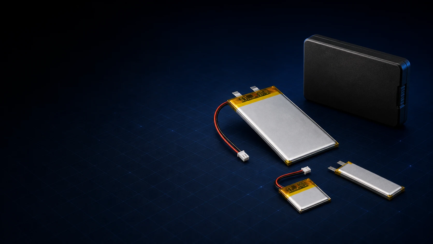
Three representative pouch-based directions for wearable, portable and professional compact devices—developed around thickness, runtime, protection, connector and service requirements.
CHOOSE A PRODUCT DIRECTION
Pouch-Led Platforms.
Different Device Interfaces.
Most compact digital and wearable projects begin with a small flat pouch cell. The main difference is how protection, wiring, fixing or a removable module must fit the device and its lifecycle.
01MINIATURE POUCH PLATFORM
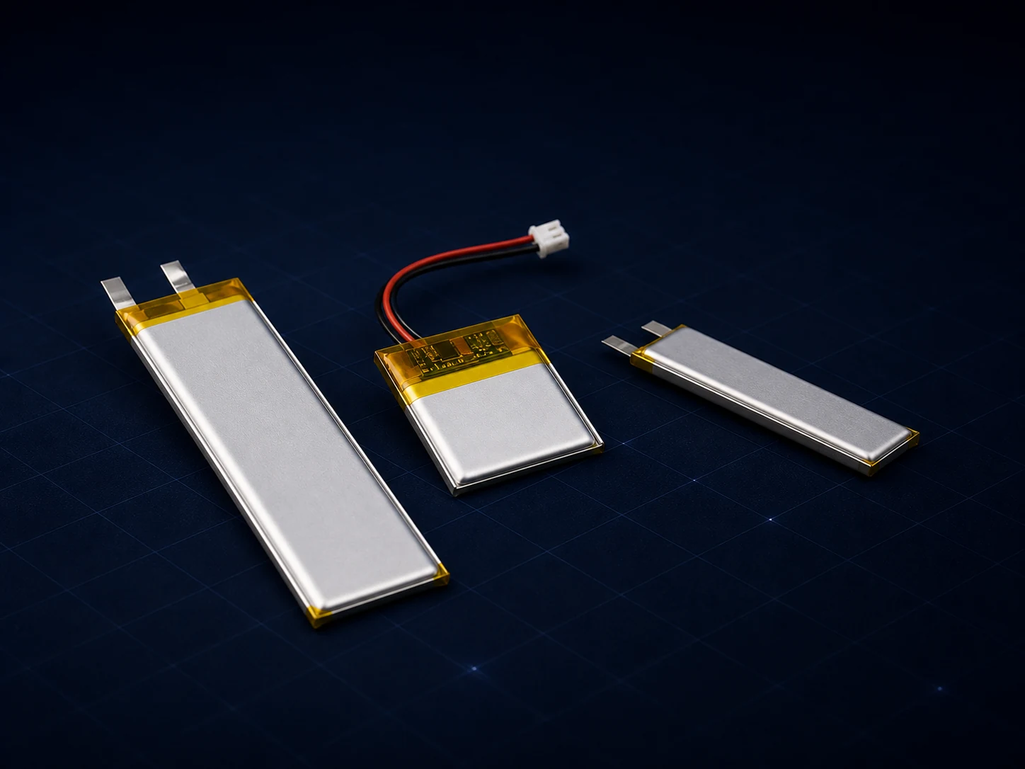
Ultra-Thin Pouch Assemblies
For wearable, sensor and very compact portable products where every millimetre of thickness, wire routing and cell position matters.
Envelope, thickness, tabs, PCM/NTC and device fixing reviewed together
02WIRED DEVICE PLATFORM
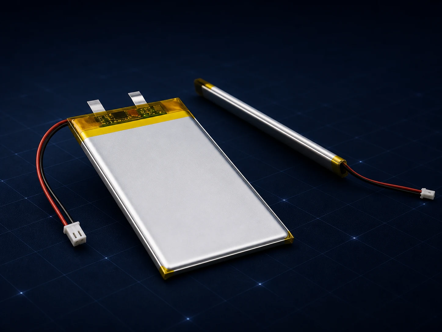
Compact Wired Pouch Packs
For professional portable electronics that need a slim pouch cell combined with protection, sensing, fine wiring and a defined connector.
Runtime, charge method, lead length and connector reviewed together
03REMOVABLE DEVICE PLATFORM
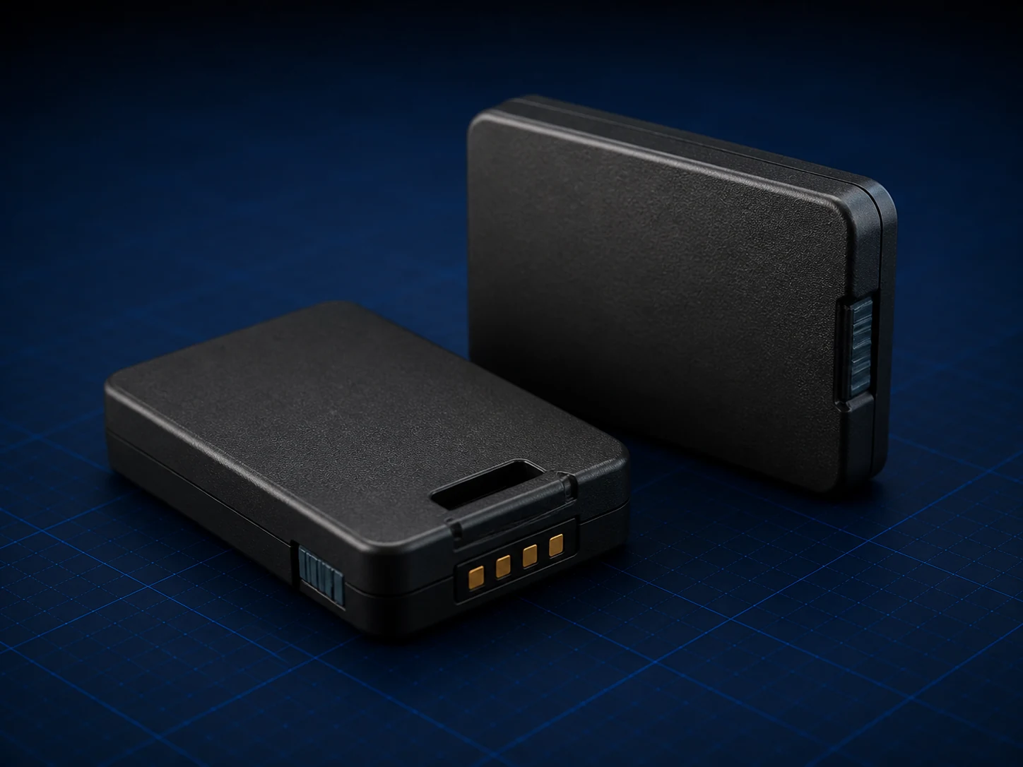
Replaceable Device Modules
For handheld, imaging and body-worn equipment that needs a serviceable slim module with a controlled housing, contacts and lifecycle path.
Housing, retention, contacts, identification and service path reviewed together
Product images show representative pouch-based directions only. Exact cell dimensions, circuit, wiring, housing, interface and specifications are confirmed after technical review.
CELL, CIRCUIT & DEVICE INTEGRATION
Build the Battery
Inside the Real Envelope.
For compact electronics, the battery is usually a flat pouch cell plus only the protection, sensing, insulation and interface the device actually needs. Very small cylindrical or button formats remain special cases rather than the main platform.
01
Device Envelope & Runtime
Available volume, weight limit, runtime, peak load and charging behaviour establish the battery direction.
02
Pouch Cell, Protection & Interface
Cell dimensions, PCM, NTC, insulation, fine wiring and connector are coordinated around the real device.
03
Assembly, Service & Release
Embedded fixing or removable housing, contacts, charger and lifecycle documents follow the approved configuration.
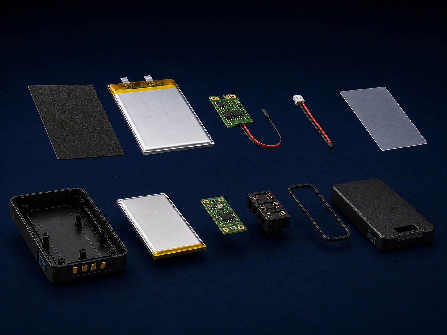
Representative embedded and removable pouch-based architectures. Final cell dimensions, electronics, wiring, insulation, housing and contacts vary by device and project requirements.
TECHNICAL REVIEW STARTS WITH
Six inputs connect the device envelope to the battery, charging and controlled release direction.
01
Space & Weight
02
Runtime & Load
03
Protection & Sensing
04
Wiring & Connector
05
Embedded or Removable
06
SKU & Lifecycle
VALIDATION & DOCUMENTATION
Release Against the
Device, Not a Generic Size.
A compact battery cannot be selected from length, width and capacity alone. The released configuration follows the real device, charging method, environment, service path and target-market responsibility.
01
Device Requirement Review
Device space, load, runtime, charging, environment and target market.
02
Prototype & Fit Check
Pouch dimensions, wiring, connector, fixing or module interface.
03
Electrical & Device Validation
Runtime, temperature, protection response, charging and intended use.
04
Controlled Product Release
Approved configuration, traceability and project document path.
REPRESENTATIVE PROJECT EVIDENCE
Agreed device requirement record
Electrical, fit and runtime test record
Approved configuration and release path
BEST FIT
Projects This Series Is Built For
- Wearable, sensor and compact smart-hardware OEM projects
- Professional portable, imaging and healthcare-device projects
- Handheld and body-worn equipment with a defined interface
PROJECT BOUNDARY
Requests That Need a Different Path
- Unauthorized copies of closed branded battery interfaces
- One-off phone, earbud or generic power-bank replacement purchases
- Capacity-only requests without device, charging or space information
START A COMPACT DEVICE BATTERY PROJECT
Share the Device,
Space and Runtime.
Share the closest available device drawing, load and interface information. Missing technical details can be organized during the requirement review.
USEFUL INFORMATION FOR THE FIRST REVIEW
01
Device type and intended use
02
Available battery envelope and weight limit
03
Voltage window, energy and runtime target
04
Typical load, peak current and standby profile
05
Connector, charging method and service path
06
Annual volume, target market and lifecycle plan