
DIGITAL & WEARABLE ELECTRONICS BATTERY APPLICATIONS
Battery Solutions Built Around the Device, Space and Use Cycle.
Define the product form, internal space, active and standby load, charging path, connector and service model first. Then coordinate the battery and validation plan around the complete electronic device.
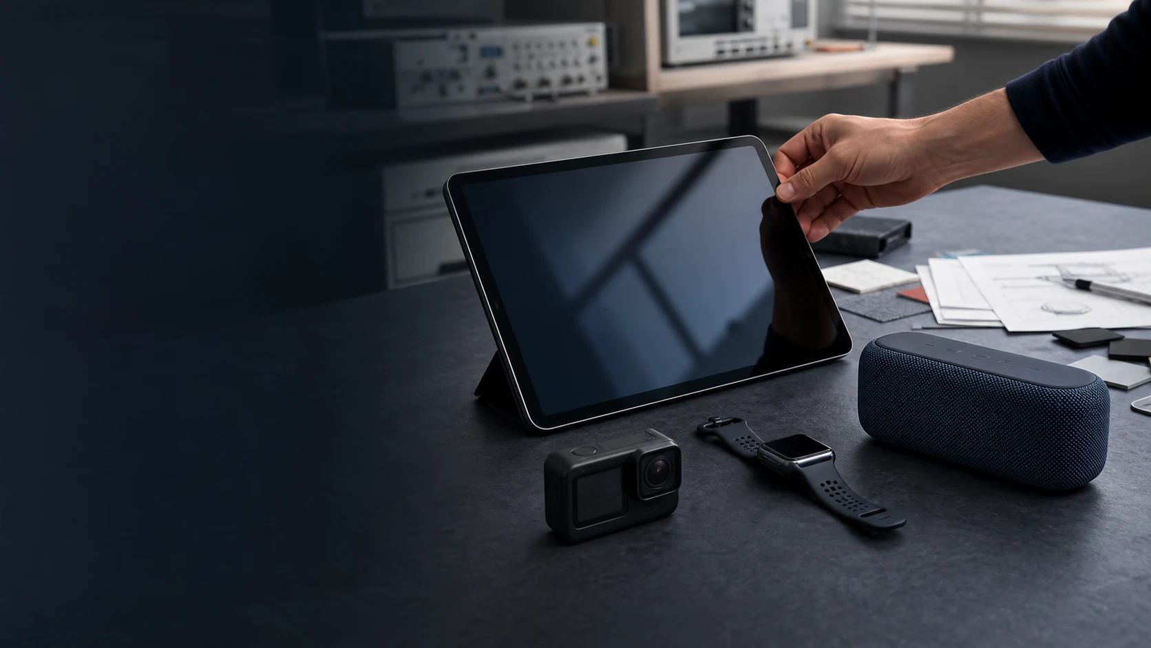
FOUR DEVICE CONTEXTS
Similar-Sized Devices Can Need
Very Different Batteries.
Select a device context to see its use cycle, battery priorities and validation focus. These are review starting points—not fixed pack specifications.
SELECTED CONTEXT · 01
Tablets & Handheld Electronics
Tablets, portable displays, smart controllers and defined handheld products combine thin packaging with mixed active, wireless, standby and charging behaviour.
- Use & Integration
Display, processing, wireless and idle modes repeated across daily use and charging cycles.
Internal space, charging path, connector or FPC, fixing method and device service strategy.
- Battery & Load
Usable runtime, thin profile and balanced mass inside the complete device envelope.
Changing active demand with display, processor and wireless peaks plus longer standby periods.
- Validation Focus
Representative active and standby cycles, charging, temperature, fit and handling checks.
- Thin envelope
- Mixed use cycle
- Device integration
SELECTED CONTEXT · 02
Compact Imaging Devices
Compact cameras, action cameras and small creator devices combine capture, processing, display and wireless transfer inside a tightly controlled form factor.
- Use & Integration
Capture and recording sessions alternate with preview, processing, transfer, idle and charging.
Device envelope, battery door or embedded fixing, contacts, retention and charger workflow.
- Battery & Load
Compact usable energy with thermal margin and a controlled charging or module relationship.
Intermittent processor and sensor peaks mixed with display, recording and wireless demand.
- Validation Focus
Recording and capture cycles, peak demand, temperature, contacts and repeated handling checks.
- Compact energy
- Intermittent peaks
- Removable or built-in
SELECTED CONTEXT · 03
Wearable Electronics
Smartwatches, fitness trackers and defined body-worn devices add thin or shaped space, low mass, skin-side temperature and sealing constraints.
- Use & Integration
Long standby with sensing, display and wireless activity plus periodic user interaction and charging.
Curved or thin enclosure, strap or fixing, skin contact, charge fixture and repair approach.
- Battery & Load
Thin, light integration with controlled temperature, reliable charging and practical sealing.
Low average demand with sensing, display, radio and processor peaks over a long wear cycle.
- Validation Focus
Representative wear and charge cycles, temperature, sweat or water exposure, fixing and lifecycle checks.
- Low mass
- Body-worn thermal
- Sealing & charging
SELECTED CONTEXT · 04
Portable Audio Devices
Compact speakers, over-ear headsets, recorders and defined portable audio products combine sustained playback with wireless, standby and charging cycles.
- Use & Integration
Sustained playback and connectivity mixed with volume peaks, standby, transport and charging.
Acoustic chamber, battery location, vibration, wiring, controls, connector and charging path.
- Battery & Load
Predictable runtime without compromising acoustic volume, product balance or service access.
Continuous audio and wireless demand with changing amplifier peaks and idle behaviour.
- Validation Focus
Playback and standby cycles, peak volume load, temperature, vibration, connector and charging checks.
- Playback runtime
- Acoustic space
- Charging & service
FROM DEVICE DATA TO A BATTERY BRIEF
Start With How the Device Is Built, Used and Charged.
A useful first review does not require a finished battery drawing. It does require enough device, electronics and use-cycle information to distinguish a real constraint from a target that can still move.
MOST USEFUL EARLY EVIDENCE
A device envelope or CAD view, representative current logs, charging information and an actual device or electronics sample are especially useful when available.
INPUTS FOR THE FIRST REVIEW
ONE CONNECTED PROJECT PATH
From Project Input to Defined Release.
The same project information moves through one connected review path. Each step narrows uncertainty and defines the evidence needed for the next decision.
01
Project Input
Device space, operating modes, runtime and charging path.
02
Technical Review
Energy and form envelope; integration and temperature risks.
03
System Validation
Device cycles, charging, fit and environmental evidence.
04
Defined Release
Approved combinations, operating limits, records and responsibilities.
PROJECT-SPECIFIC VALIDATION
Move Forward Through
Three Clear Decision Gates.
Each stage connects the device input to visible evidence and an agreed decision. Exact tests, records and responsibilities are defined for the project rather than implied as universal.
01
Agree the Device & Use Brief
PROJECT INPUT
Device type, operating modes, internal space, runtime, charging path, environment and available load data.
REVIEW EVIDENCE
A shared device constraint list, missing-data list and proposed review scope.
DECISION GATE
The project team agrees what must be evaluated and what remains conditional.
02
Check Pack, Electronics & Mechanical Integration
PROJECT INPUT
Pack space, fixing or module structure, wiring or contacts, protection, sensing, charging and representative loads.
REVIEW EVIDENCE
Project-specific fit, interface, charge behaviour, protection response and temperature records.
DECISION GATE
Open integration issues are closed or explicitly carried into device trials.
03
Validate Use Cycle, Reliability & Release
PROJECT INPUT
Agreed device cycle, handling, environment, charging process, service path and trial responsibilities.
REVIEW EVIDENCE
Recorded device-level runtime, charging, environmental and service behaviour against the agreed conditions.
DECISION GATE
The approved device, battery configuration, operating limits and remaining responsibilities are documented.
RELEASE SCOPE
Define What Approval Actually Covers.
PROJECT FIT
Defined B2B Device Projects Come First.
Best Fit for This Page
- New owned or authorized digital and wearable product programs.
- Small and mid-sized brands or OEMs with defined enclosure, electronics and charging information.
- Product refresh or authorized aftersales projects with actual devices, samples and interface data.
- Projects with a realistic sample path, annual volume, target market and lifecycle plan.
Requests That Need a Different Path
- Single consumer replacement-battery purchases.
- Unauthorized copies or compatibility claims for closed branded devices.
- Generic phone, TWS-earbud or power-bank price inquiries without a defined device project.
- Capacity-only requests without enclosure, electronics, charging or commercial information.
BEFORE A TECHNICAL REVIEW
Common Project Questions.
Can the battery be developed for a thin or shaped wearable enclosure?
Potentially. The review must consider the real space, cell position, protection and sensing, skin-side temperature, sealing, fixing, charging and service approach before confirming a direction.
Can an existing connector, FPC, charging circuit or dock be reused?
Potentially, but only after checking pin definition, polarity, current and temperature limits, mechanical fit, strain relief, charger behaviour, sample consistency and interface ownership.
How are active, peak, standby and charging behaviour evaluated?
Representative current logs and controlled device cycles are used to review active modes, short peaks, wireless or display demand, long standby, charging and temperature response rather than relying on capacity alone.
What should be considered for body-worn or water-exposed devices?
The project should define skin-contact temperature, sealing, sweat or water exposure, charging method, fixing, impact, cleaning and post-test functional checks for the actual product category.
START WITH THE DEVICE
Share the Product, Space, Load and Charging Path.
You do not need a finished battery specification. Send the exact device context and the best available space, load, charging and interface information, and we can review the next technical step.
FOUR DETAILS TO START
Device & Intended Use
Space & Runtime
Connector & Assembly
Charging & Target Market
Defined B2B device projects only. Compatibility, validation and market requirements remain project-specific.